
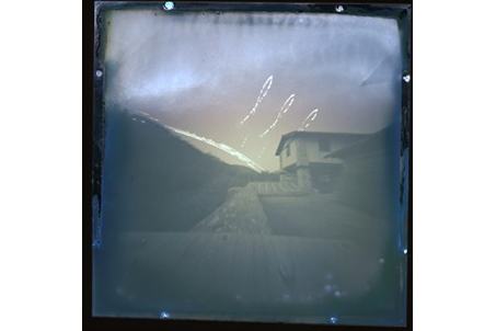
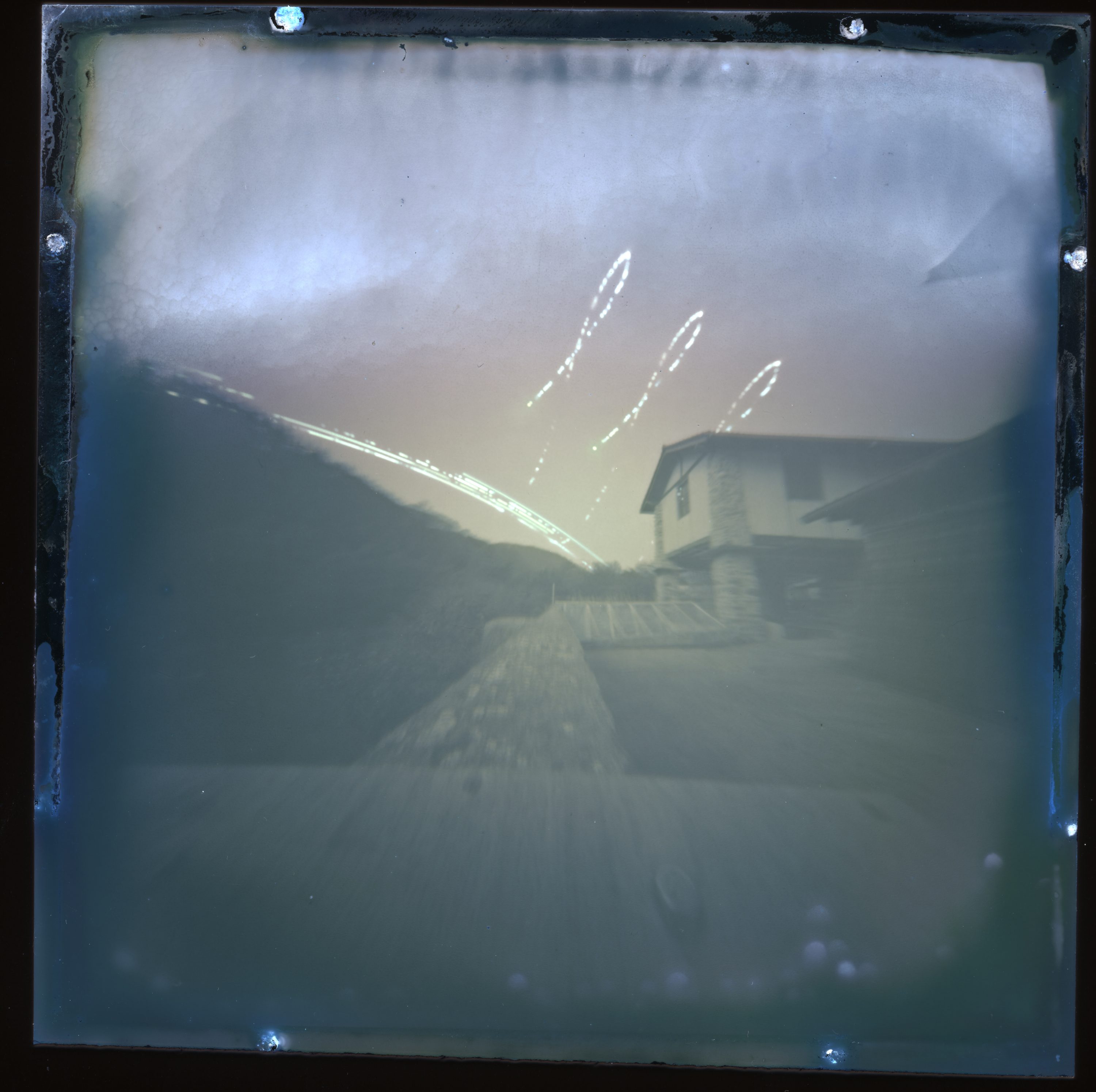
Solargraphy is a concept and a photographic practice based on the observation of the sun’s path in the sky (different in every place on earth) and its effect on the landscape. It is captured by a specific procedure that combines pinhole photography, digital processing and webcasting. Typically, undeveloped photographic paper, a pinhole camera and a scanner are used in order to create images of the sun’s daily path across the sky. They are taken with a long exposure, ranging from several hours to many months. Since the beginning, there has been constant sharing, broadcasting and collaborating by enthusiasts around the world, fueled by the means of the internet.
The purpose of this project is to automatize the capture of the Solar Analemma, the curve that describes the position of the sun in the sky when it is observed at the same time of the day (time zone), every day of the year, from the same place. Analemma forms a curve that is usually roughly shaped as an eight (8) or a lemniscate shape.
Capturing the Analemma manually requires taking a picture at the same time every day of the year. It is a task often infeasible since we might not always be available to do so. The automated camera is therefore a very useful tool for this practice since it allows us to be able to take pictures always at the same time.
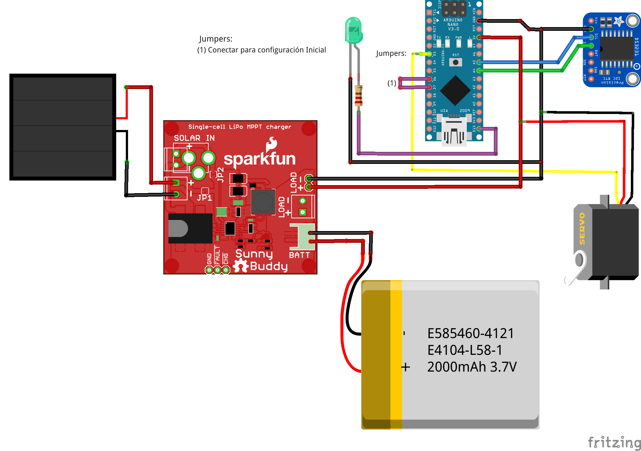
During this project we have made an Arduino controlled camera using an RTC (real time clock) for time synchronization. Equipped with a battery and a solar panel for a total autonomous system, it does not need external power sources. Thus, it allows us to install it in places of difficult access and it is suitable for capturing the sun without obstructions. The camera shutter (of pinhole type) is controlled by a 9gr servo that moves the piece that covers the camera hole.
Step by step
- Arduino Nano
- RTC DS3231 modul
- SparkFun SunnyBuddy
- Solar panel
- Lipo 1S 2000 mAh batery
- Servo 9gr
- LED 5mm
- 220 Ohm Resistence
- Connection cable
#include <DS3231.h>
#include <Wire.h>
#include <Servo.h>
#include <EEPROM.h>
#include <LowPower.h>

// Soft reset
#define RESTART asm("jmp 0x0000")

#define PIN_ACT_OBTURADOR         3  // Arduino D3
#define PIN_CONFIGURACION_I       6 // D6
#define PIN_CONFIGURACION_O       7 // D7

#define EEPROM_NUM_ESTADOS        0
#define EEPROM_ESTADO_ACT         1
#define EEPROM_TIMEDATA_START     2

#define ANGULO_APERTURA           130
#define ANGULO_CIERRE             5

DS3231 rtc;
Servo obturador;

byte anyo;
byte mes;
byte dia;
byte dia_semana;
byte hora;
byte minuto;
bool h12, pm, siglo;
byte ADay, AHour, AMinute, ASecond, ABits;
bool ADy, A12h, Apm;
struct rst_info* reset_info;
byte estado_actual;
byte num_estados;
int init_mode;

void setup() {
  delay(1);

  // Iniciamos el I2C
  Wire.begin();
  // Aseguramos que estamos en modo de 24h
  rtc.setClockMode(false);
  siglo = false;

  // LED
  pinMode(LED_BUILTIN, OUTPUT);
  digitalWrite(LED_BUILTIN, LOW);

  // IO
  pinMode(PIN_CONFIGURACION_I, INPUT_PULLUP);
  pinMode(PIN_CONFIGURACION_O, OUTPUT);
  // set to LOW
  digitalWrite(PIN_CONFIGURACION_O, LOW);

  // Y el puerto serie
  Serial.begin(115200);
  Serial.println();
  Serial.println("Iniciando...");

  // Vemos si tenemos que reiniciar, entrar en la configuración o continuar.
  init_mode = digitalRead(PIN_CONFIGURACION_I);
  Serial.print("Configuración Leida: ");
  Serial.println(init_mode);

  if (!init_mode) {
    // configuración?
    delay(3000); // esperamos 3 segundos
    if (!digitalRead(PIN_CONFIGURACION_I)) {
      // configuración por puerto serie
      digitalWrite(LED_BUILTIN, HIGH); // LED continuo
      Serial.println("Esperando configuración...");
      char serial_buffer[255];
      char c = 0;
      int counter = 0;
      while ((c != 255) && (counter < 100)) {
          if (Serial.available() > 0) {
            c = Serial.read();
            serial_buffer[counter] = c;
            counter++;
          }
      }
      // check marker
      if (serial_buffer[0] != 'x') {
          Serial.println("Bad configuration");
      }
      for(;;);
    } else {
      // reiniciamos al estado inicial y continuamos
      Serial.println("Iniciando desde cero...");

      // parpadeo largo
      for (int i = 0; i < 20; i++) {
        digitalWrite(LED_BUILTIN, HIGH);
        delay(100);
        digitalWrite(LED_BUILTIN, LOW);
        delay(100);
      }
      // reiniciamos el estado
      // estado_actual = 0;
      EEPROM.write(EEPROM_ESTADO_ACT, estado_actual);
      EEPROM.write(EEPROM_NUM_ESTADOS, 2);
      EEPROM.write(EEPROM_TIMEDATA_START, 11);
      EEPROM.write(EEPROM_TIMEDATA_START+1, 15);
      EEPROM.write(EEPROM_TIMEDATA_START+2, 11);
      EEPROM.write(EEPROM_TIMEDATA_START+3, 20);

      // obturador cerrado
      obturador.attach(PIN_ACT_OBTURADOR);
      obturador.write(ANGULO_CIERRE);
      delay(250);
      obturador.detach();

      // ponemos la primera alarma
      hora = EEPROM.read(EEPROM_TIMEDATA_START);
      minuto = EEPROM.read(EEPROM_TIMEDATA_START+1);

      rtc.setA1Time(0, hora, minuto,
                    0, 0x8, false, false, false);
      // Y la activamos
      rtc.turnOnAlarm(1);

    }
  }

  // modo normal
  // parpadeo
  digitalWrite(LED_BUILTIN, HIGH);
  delay(100);
  digitalWrite(LED_BUILTIN, LOW);

  Serial.println("Continuando...");
  // Cargamos datos desde la eeprom
  num_estados = EEPROM.read(EEPROM_NUM_ESTADOS);
  estado_actual = EEPROM.read(EEPROM_ESTADO_ACT);
  Serial.print("Estado leido: "); Serial.println(estado_actual);
  Serial.print("Num estados: "); Serial.println(num_estados);

  // Leemos el RTC
  mes = rtc.getMonth(siglo);
  dia_semana = rtc.getDoW();
  dia = rtc.getDate();
  hora = rtc.getHour(h12, pm);
  minuto = rtc.getMinute();

  Serial.println(); Serial.print("---- ");
  Serial.print(mes); Serial.print("/"); Serial.print(dia); Serial.print(" ");
  Serial.print(hora); Serial.print(":"); Serial.println(minuto);
  delay(500);

  if (rtc.checkAlarmEnabled(1)) {
    Serial.println("\nAlarm 1 enabled");
  }

  Serial.print("Alarm 1: ");
  rtc.getA1Time(ADay, AHour, AMinute, ASecond, ABits, ADy, A12h, Apm);
  Serial.print(ADay, DEC);
  if (ADy) {
    Serial.print(" DoW");
  } else {
    Serial.print(" Date");
  }
  Serial.print(' ');
  Serial.print(AHour, DEC);
  Serial.print(' ');
  Serial.print(AMinute, DEC);
  Serial.print(' ');
  Serial.print(ASecond, DEC);
  Serial.print(' ');
  if (A12h) {
    if (Apm) {
      Serial.print("pm ");
    } else {
      Serial.print("am ");
    }
  }
  Serial.print(' ');
  Serial.println(ABits, BIN);
}

void loop() {
  // Comprobamos alarma
  if (rtc.checkIfAlarm(1)) {
    Serial.println("Alarma!");
    // dependiendo de si el estado actual es par o impar, abrimos o cerramos el obturador
    obturador.attach(PIN_ACT_OBTURADOR);
    if (estado_actual % 2 == 0) {
      obturador.write(ANGULO_APERTURA);
      Serial.println("Abriendo...");
    } else {
      obturador.write(ANGULO_CIERRE);
      Serial.println("Cerrando...");
    }
    delay(250);
    obturador.detach();

    // pasamos al siguiente estado
    estado_actual = estado_actual + 1;
    if (estado_actual > num_estados) {
        estado_actual = 0;
    }

    hora = EEPROM.read(EEPROM_TIMEDATA_START + (estado_actual*2));
    minuto = EEPROM.read(EEPROM_TIMEDATA_START + (estado_actual*2) + 1);

    // ponemos la nueva alarma
    dia_semana = rtc.getDoW();
    rtc.setA1Time(0, hora, minuto,
                        0, 0x8, false, false, false);
    rtc.turnOnAlarm(1);
  }

  Serial.println("Sleep...");
  // a dormir (bajo consumo)
  Serial.flush(); // wait for serial
  for (int i = 0 ;  i  <  15 ; i++) {
    LowPower.powerDown(SLEEP_2S, ADC_OFF, BOD_OFF);
  }
  RESTART;
}

After assembling the circuit described in the diagram, and making sure that the RTC already has the correct time (using the example of the RTC DS3231 library to set it in time), it will be necessary to program it with the Arduino code listed, and for this we will first have to configure in the code the desired hours for the shots in its first section.
To do this, we will modify the hours, minutes and seconds of each shot in the times section, and we will comment or uncomment the TOMA_SOL2 and TOMA_SOL3 sequences depending on whether we want one, two or three shots (and therefore anomalies as with the example image in the gallery).
Then we will program the arduino with this code and mount the system inside the camera that we are going to use. We recommend using a totally watertight box, possibly a PVC connection box suitable for the size of the socket we want to make (depending on our pinhole, focal length, etc.), and we will glue the servo with a piece that when the servo is in position 0º cover the shutter. We can do some test first with the servo control example included in the arduino environment to see the corresponding positions and the direction of movement.
We will place the solar panel oriented towards the south and with an approximate angle with respect to the horizon at the latitude where we are to maximize its solar exposure.
Before closing the camera, we must restart the code. To do this, we will connect the pins marked in the diagram as I / O to each other and we will power the board, so the program will understand that it has to start from scratch. Now we will disconnect everything, including the I / O pins and we will power the system again, which will now be ready to take the shots automatically. We can check if the system is alive by looking at the schematic LED, which should blink approximately every 30 seconds.