
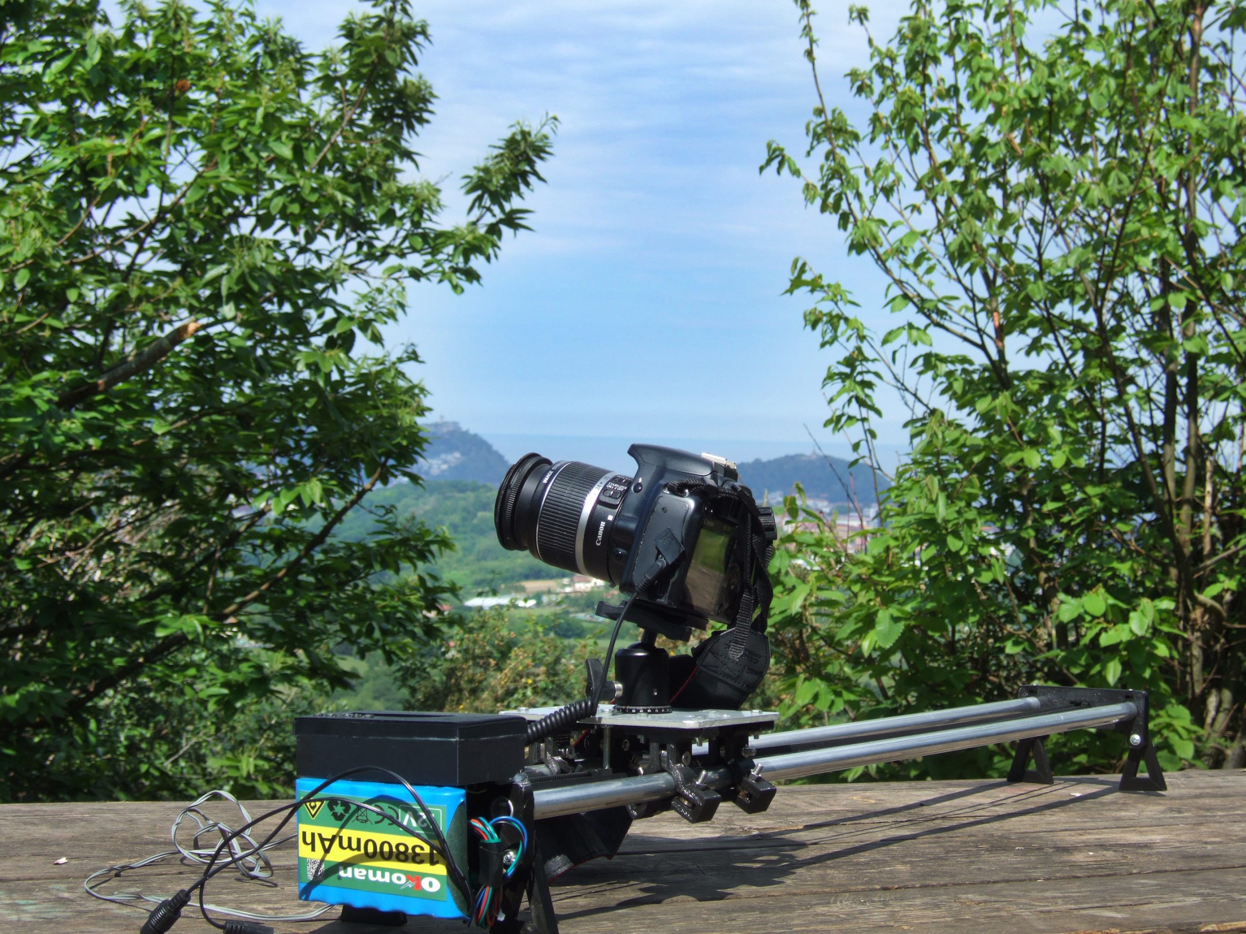
What is a slider?
A slider is a slide rail for photographic or videographic use that allows very precise and controlled camera movements, being able to create interesting narratives and descriptive plans.
The presented motorized slider will allow us to automate and control camera movements, its shooting sequence and the photographic exposure number.
The idea is to build a simple and inexpensive linear displacement device that is smooth, accurate and stable enough to take intermittence pictures, time-lapses, or to simply have the video camera scrolling.
Step by step
You will need the following material to build the Slider:
- 2 aluminum tubes of 16mm outer section, by 1000mm in length.
- Toothed belt of 2 meters in length by 6mm with their respective
bearings and pulleys. - Motor paso a paso Nema 17 12V
- Interruptor fin de carrera
- Arduino Uno
- Display (LCD screen)
- Motor controller
- Battery 12V
- LED 940 nanometer (Notes: To execute infrared camera shooting automatically (valid for Canon and Nikon cameras). This led has to have a protection resistance that reduces from 5 volts to 3 volts, typically 20 milliamps and 220 ohms, welded to its short leg)
- Ball head
- Ball bearings (Notes: 10pcs/lot Flange Ball Bearing 623zz 624zz 625zz Deep Groove Pulley Wheel with Flanges for 3D printer parts)
- Nuts, screws and differents sizes washers.
Soldering iron, hot glue, screwdrivers and drill with a 2.5mm or 3mm bit, and scissors.
- Skate support: part already printed for the support of the sliding platform of the slider, to which the bearings will have to be screwed.


2. Side support 1, with a pulley for the belt. In the following image, we show the triangular legs for both sides of the supports, which we will join them with wing nuts, in this way we can fold them if necessary.

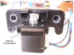
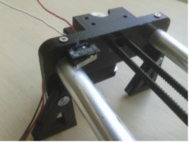
3. Note, the motor already screwed to the support with the shim (made of plywood) to favor the fixation, and the aluminum tubes embedded in the support2 on which the camera platform rests, with the sliding pieces (4) that they house three bearings each.

4. Motor attached to the bracket, with a 2.5mm plywood shim, to free the deck from the axle and allow the screws (3mm diameter and 6mm long) to penetrate far enough to secure the motor.
5. Limit switch in place. For this, two holes have been drilled with a 2.5 drill bit, in order to pass the cables through support 1 to the arduino and later it has been glued with hot glue to hold it.
3D part files: 3D Slider files
Electronic control:


2.- Motor controller: it is convenient, if you have one, to stick a heat sink on the controller chip, as it becomes quite hot.

3.- The printed box to house the LCD screen with the Arduino and the motor controller.
4.- At the bottom we have placed the batteries glued with velcro to the side of the motor, in order to be able to extract them easily for recharging.
5.- The purple post (optional) is a flexible wire covered with foam for the tie (with adhesive tape / a rubber band etc.) of the infrared led, which generates a firing code in the camera (included in the programming and valid for Canon and Nikon cameras), so this must be placed in front of the camera’s receiver. This led can be substituted for the classic trigger pin connector.
You will find Arduino programming on the GitHub portal