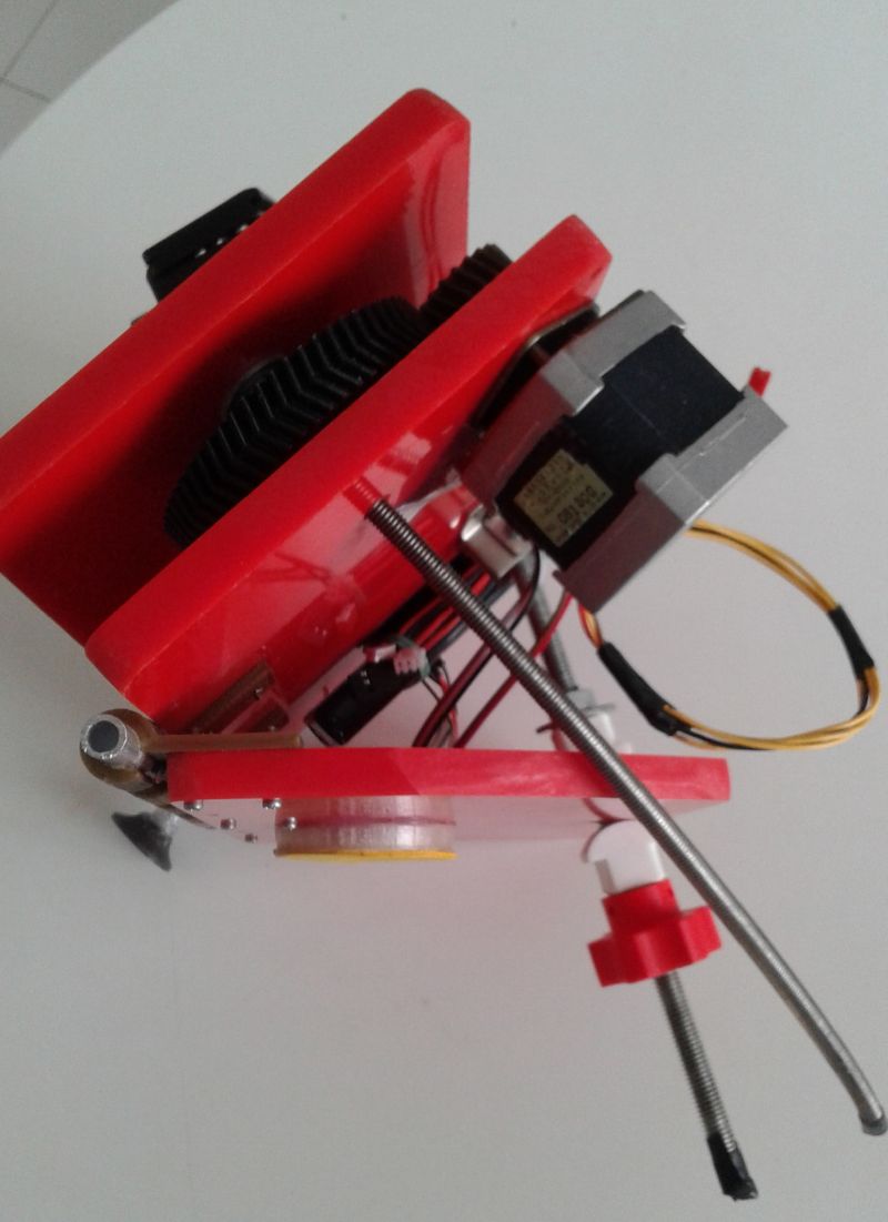
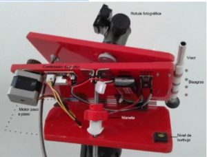
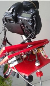
The purpose of this project is to introduce us to the world of astrophotography at a low cost by constructing a device called “equatorial tables.” This device allows us to capture long-exposure photographs while counteracting the Earth’s rotational movement (axial rotation), ensuring that celestial objects appear sharp and not blurred due to this effect.
Step by step
First, it’s important to note that photography for astronomical purposes, or astrophotography, marked a significant breakthrough for this science as early as the 18th century.
From the earliest “daguerreotypes” to modern advancements, astrophotography has enabled professional discoveries, particularly with the advent of digital photography. Digital technology, accessible to any user, allows us to use long-exposure techniques and subsequent image processing to reveal a multitude of celestial objects that astonishingly emerge before us. This is due to the accumulation of photons on the camera’s sensor while the shutter remains open, unlike our vision, which cannot generate such a buildup of light. This makes it relatively easy to explore a fascinating part of nature—the night sky—which would otherwise be difficult to observe.
Equatorial tables or equatorial platforms with manual movement (Image 1) have been used by amateur astrophotographers for decades. Today, technology allows us to fully automate these devices at a very low cost, relieving the user from the demanding process of manual guiding.
It’s important to note, however, that equatorial tables have their limitations. Due to the potential imprecision in aligning with the celestial pole, it’s not recommended to use focal lengths greater than 100mm. For initial use, the classic 50mm lens is especially suitable, as its typically high luminosity ensures greater satisfaction.
Another goal of this project is to provide precise, detailed instructions so that anyone interested can build their own equatorial table. This fosters a love for astrophotography and, more broadly, for astronomical observation.
List of materials for the Equatorial Table project:
1 & 2. Tables – Made of red methacrylate (25x15x0,6 cm), but plywood (25x15x0,8 cm) can also be used.
- Price: Not specified, as recycled pieces were used.
3. Aluminum Rod – 8 mm outer diameter.
-
- Approx. Price: € 1.50 at hardware or DIY stores.
4. 3D-Printed Hinges – Nine hinges made from PLA material.
-
- Approx. Price: € 0.50 (includes the file for printing).
5. Stepper Motor – Salvaged from a discarded paper printer; new motors are available on Amazon.
-
- Approx. Price: € 12,-.
6 & 11. 3D-Printed Gear Wheels – Made from PLA material.
- Approx. Price: € 0.50 (includes the file for printing).
- The larger gear includes an embedded M6 nut.
7. Screw for Ball Head Attachment
-
- Approx. Price: € 1,-.
8. Photographic Ball Head
-
- Approx. Price: From € 15,- and up, depending on the model (e.g., AliExpress).
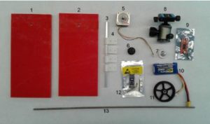
9. Motor Controller
-
- Approx. Price: € 4,-.
10. LiPo Battery (3S)
-
- Approx. Price: € 15,- (available from Banggood, Gearbest, Hobbyking, etc.).
- Alternatively, LiPo Battery (2S)
- Approx. Price: € 7,- (same retailers).
- Any other Li-ion battery with a voltage range of 7.5 V (minimum) to 24 V (maximum) can also work.
11.- Arduino
-
- Approx. Price: € 2,- (Banggood, Gearbest, AliExpress).
12. M6 Threaded Rod
-
- Approx. Price: € 1.50 at hardware or DIY stores.
Additional Items:
Screws for securing the hinges (4) to the tables (1 and 2).
13.- Photographic Nut – For tripod attachment.
-
- Approx. Price: € 0.50.
*Note: A DSLR camera with a shutter release cable or intervalometer and a photographic tripod is assumed to be already available.
With these materials, we can carry out the basic construction of the equatorial tables.
It is important to curve the 6mm threaded rod with a radius of 228.6mm. This radius should match the distance from the center of the viewing tube (placed as the axis on the hinges) to the point where the holes are drilled into the two upper boards for its placement.
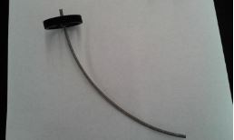
To curve the threaded rod, we can use a surface with a similar curvature, applying pressure at both ends of the rod and then cutting two sections: approximately 30 cm for the upper board and around 20 cm for the lower board.
However, we have chosen to add a third board, which will serve to stabilize the photographic tripod. This board will allow the tripod to move only in azimuth (as it will remain horizontal) and help with the alignment of the system, specifically making it easier and more precise to find the North Star in the viewfinder by adjusting the height of the third board.
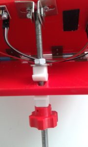
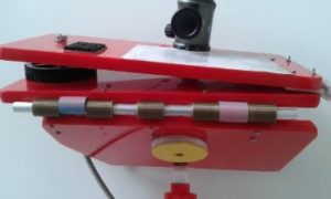
This vertical movement is achieved by overlapping a piece of threaded rod between two metal brackets (filed at both ends and drilled to pass a small screw), or simply by securing it with two nuts to the intermediate board. Additionally, a nut or 3D-printed handle will be attached to facilitate height adjustment, with a metal nut fixed inside the handle. (Figure 1).
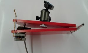
For the lower board, we partially section one end to prevent it from rubbing against the threaded rod during its movement. This board is joined to the intermediate board using five more hinges and an aluminum rod, placed longitudinally to the intermediate board, with the threaded rod centered. We also need to embed a specific nut (roughly in the center) to screw the tripod’s mounting plate onto it (Figure 2).
Figure 1
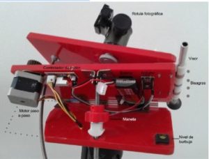
Figure 2
Files designed in FreeCAD for 3D printing:
- Tablas ecuatoriales.stp
- Tablas ecuatoriales1.FCStd
Details of the 3D-Printed Gears:
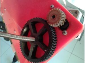
For the small gear, it must be inserted onto the motor shaft, ensuring it generates traction. For the large gear, a corresponding metric nut should be inserted and glued into its center (referred to as the “egg” of the gear).
Digital files:
- bisagra.stl
- coronas dentadas.stl
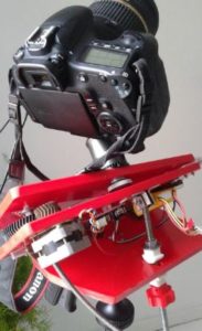
We provide the Arduino configuration file to achieve the correct motor speed (360º in 24 hours) for the stepper motor. To get started, you need to download the free Arduino software from the following link.
Once the application is downloaded and installed, you can connect the Arduino Nano to your computer and upload the following file: tabla_eq1_ajustado.ino
#define PAUSA_VELOCIDAD 12,5
#define DIRECTION 3
#define STEP 2
void setup() {
pinMode(DIRECTION, OUTPUT);
pinMode(STEP, OUTPUT);
digitalWrite(DIRECTION, LOW);
digitalWrite(STEP, LOW);
}
void loop() {
digitalWrite(STEP, HIGH);
delay(1);
digitalWrite(STEP, LOW);
delay(PAUSA_VELOCIDAD); }

