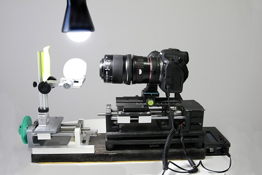
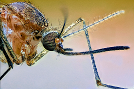
Construction of a motorized track or rail for extreme macro photography (>1:1) using the “focus stacking” technology. The technology consists in using multiple photograms with different accurately controlled and previously defined focal lengths, that help achieving a greater depth of field.
Step by step
It needs the following materials to build and set up the automized camera slider for extreme macro photography:
- Linear bearings with rail
- Motor clamp shaft
- Lead screw rod
- Lead screw T8 200mm (1mm de paso)
- Slide bars 20mm
- Motor nema 17
- Arduino Uno
- LCD screen
- Motor controller
- (Limit switch)
- Optocoupler (10 unities)
- Resistance 200 milliamps
- Cable release for camera
- Famale plug adapter (2 unities)
- Camera speedlite
The following files facilitate the 3D-prints for the construction of the slider or rail:
Image of soporte1 (frame 1), already printed with bearing for spindle and bearing rods
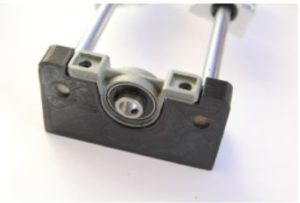
Image of soporte2 (frame 2) with the motor (including the clamp shaft) already screwed. Next to it the limit switch with the cables previously welded
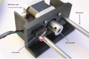
Image of the printed camera rig, with the camera shoe already attached. This should be bolted to the linear bearings. (in the 3D design of the camera platform part, the receptacle for the spindle is included)
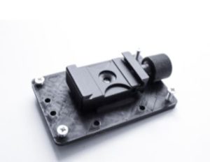
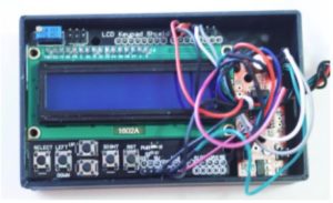
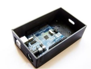
Image of the box as a remote control, which houses the Arduino, on which the LCD screen must be placed, and on the right side the motor controller.
Note that on the left side of the image there are two holes, one for the connection of the Arduino to the computer via USB, the other for the 12v power supply, although it could be working between 9 and 14 volts. On the other side there is a slot through which all the wiring inside has to pass (those of the motor, those of the limit switch and those of the camera trigger).
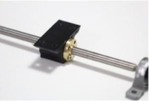
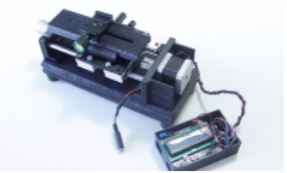
Finished rail. The side supports have already been screwed to a wooden base with small rubber feet to reduce vibrations.
